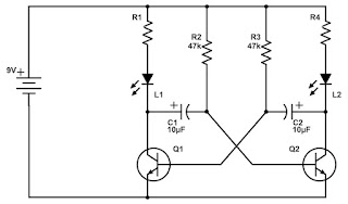
My attempt at the "Eternity LED Blinkers"
A few months ago, my friend ordered some LED's from Ebay. We thought nothing of them, but, we noticed that they are very low power. Trying to see how low we can go with the current, we noticed that they are even visible at a few micro-Amps! In the case of the white LED's you can go as low as 1-2 μA, but they become visible enough at about 30-50uA!
Since my purpose is not to do any advertising, I could post a picture of the LED's in question and you can do you buying from any seller you want, maybe using Google's reverse image search.
A few months after, I wanted to make a astable multivibrator circuit using these LED's and some very high series resistors, to see how long the battery is lasting. The results were amazing!
I have built a variation of this schematic, but I knew from the start that the bipolar transistor take a lot of current. Then, I have built the same schematic using MOSFET transistors
The Best usage I have found for this is a lithium Ion battery indicator!.
By playing with the values of R5-R6 or R1-R3, you can get a very cool behavior: LED1 and LED2 between 4-4.2V, blinking between 3.3V-3.9V and off under 3.3V. This made a very cool indicator. Just require a pot to adjust the desired values!. Also, this runs about 5 minutes from a 2200uf Capacitor, which will be my benchmark from now on!
Moving on, I had thought about using just a single LED and blinking it. It was then when I have found this post! (Post in German language, use Google Translate).
From here, I have found this amazing schematic:
This schematic works OK, but it's still using too much power .This can be blamed on several things, including the power hungry leds. So, let's improve the schematic a little bit:
Also, I wanted an extra voltage doubler for the white LED, so I've added another charge pump.
This schematic work as it should. With the low power LED and the 2200uF capacitor, it works for about 25-30 minutes! The 2 P channel MOSFET are logic level ones. In my case they are : FDN340P. the 2 MOSFET can be replaced with PNP transistors, but you also need to replace R10 and R11 with resistors varying from 1M Ohm to 4.7 M Ohm.
These schematic work very well at 1.5v batteries. Personally, i recommend some "Energizer Ultimate Lithium" that have a shelf life of about 20 years.
Another schematic that I have found and built is this one.
This is not mine, and I can say that the author is brilliant. The flashing part with 4001 is very well designed. Unfortunately, the "Joule Thief" part is not, as "Joule Thiefs" are doing exactly that: stealing energy and wasting it. But, we can use the first part of it... Again, tested the schematic with a 2200uF capacitor and it ran only a few seconds..
Lets cover a bit the so called "Joule Thief's"
Joule Thief's
I won`t go so much into dept on how a Joule thief work. But this is the standard schematic of one:
In a nutshell, the transistor open because of the current that flows trough R, inducting a EM field trough the TR, which induces a negative voltage into the base coil, that closes the transistor. The EM field also get's collected with a second winding of the transformer and lights up the LED.
This works, but the process is not very efficient especially at low currents. in my tests, to get about 6 mA at 3.5v from a 1.5v battery, it required about 35mA. Without the LED the drawn current drops just by about 1 or 2 mA. This get`s worse at even lower currents.
In other words, "Joule Thief's" do exactly as they say: They steal energy.
For efficiency we would require a specialized step-up IC with high efficiency and low quiescent current.Enter MAX1724. 1.5μA IQ, up to 90 percent efficiency! In other words, better than a DIY "Joule Thief". From the datasheet, we get the schematic. I have chosen the 3.3v version, as it's enough for the white LED.
Now, Now, if only we can find a low power IC flasher.... hmmm...
in this schematic, I have used the schematic from the 10 year flasher in the link I've posted earlier, but instead of the 4001 I have used the low power 74HC02 IC, which draws even lower power.
Jumper 1 and 2 bypasses the IC, if you use a 3.6v lithium high shelf life battery!
After playing with this version, I could not get more than 5 minutes from a 2200uF capacitor at 1.5v.
At first, I have build one without PCB. I have use silicone mold for (for making cakes). I gotta say it looks pretty nice.
The values of the resistors are a bit different from the schematic, as It went trough a lot of changes. Overall, It looks very nice. The battery I have used is a Energizer Ultimate Lithium, and should have a shelf life of minimum 20 years.
I have also designed and built PCB, but, I could say the look best if they are built without a PCB.
Conclusions:
In the end , I've realized that 2 schematic stand out:
This one. Because of it's simplicity and efficiency ! On a 2200uf capacitor charged with 1.5v, it lasts for about 20 min!
 Finally, second best is this one:
My experience with these ultra low power LED's is a very pleasant one. And all my experiments have shown that when you are talking about micro-amps, capacitive doubler is the way to go, because inductor based step-up are not so efficient!
Giving the high shelf life of the battery, the blinker should work for a few tens of years! Good Luck!


